The Drum Scan Saga
This is the story of a boy and a drum scanner. Another title that comes to mind is, "The unbearable sadness of engineering." This page is for people who like machines and like knowing how they work. It's also about how modern electronic technology goes out of date in an instant.
The photos below are from a ScanMate 5000 drum scanner which came into my posession a few months ago. This happened only because the machine was playing dead at the time. I took the beast home to my cool basement and amazingly, it woke up and worked just fine... for a while. Just like Dr. Sack's patient (played by Robert DeNiro) in "Awakenings."
Ah, but it was too good to be true. Just like DeNiro in the film, the machine descended back into slumber. And here's where the story gets sad. This was a seriously expensive machine when it was new. I can only really guess how expensive, but let's say -- far beyond my means. As far as I know these machines are no longer in production. The original manufacturer (ScanMate) is Danish and may no longer even exist. There's an outfit in Georgia (USA, red state) that still fixes them, but I'm sure I can't afford what they'd be asking for that. I'm not even sure when this machine was built. Date codes for parts inside range from 1994 to 1997.
As they say, easy come easy go. You get what you pay for, and all that. If it had been a healthy functional machine it wouldn't be mine to dissect. Ever wondered what the inside of a drum scanner looks like? Here goes.
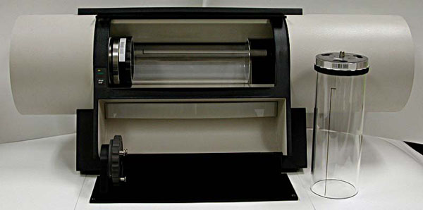
A picture of a perfectly happy, new-looking ScanMate 5000.
Not mine. Photo shamelessly ripped off from an eBay auction.
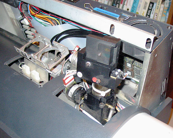
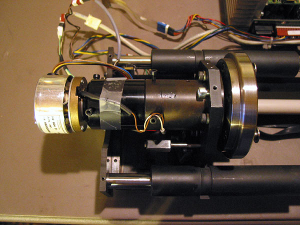
View from back of scanner, rear cover removed. The black protrusion on the right is the optical pickup. You see three fat black "wires" leaving it and disappearing into machine. These are light pipes (one each for red, green, blue) carrying the optical spot signal to the PMT tube assembly. Toward the left you see a bracket for a pair of MR-16 halogen bulbs. One of these bulbs provides the light source for film and transmissive targets. The other bulb provides the light for reflective targets.
The machine's skin. Nothing really essential here, except as skin and bones for the beast.
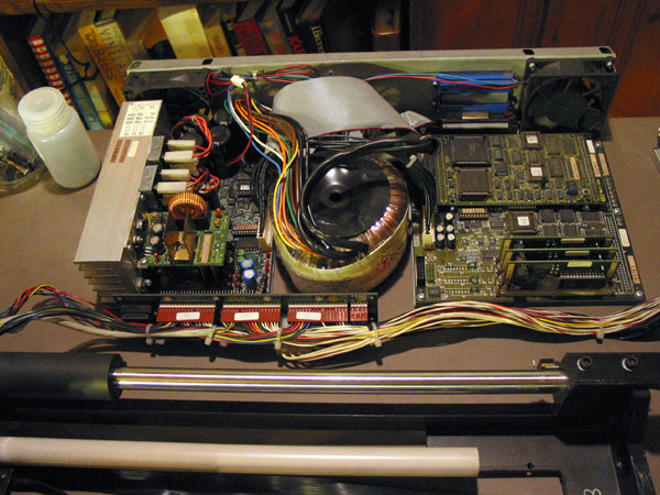
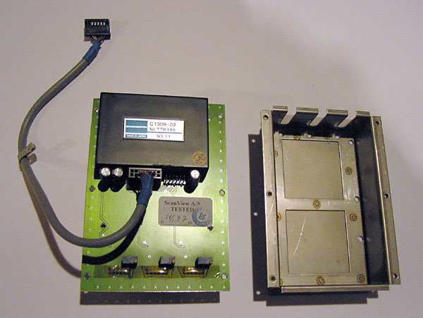
Disassembled. Electronics tray. Huge toroid transformer for an old fashioned linear power supply (on left.) Logic board is on right, with three "daughter" cards containing A/D converters and analog conditioning circuitry for the PMT tube outputs.
All of the wiring to/from the electronics tray goes through a DIN-C connnector to a small distribution circuit board. You can see the main part of the harness running across the photo.
In the foreground you see part of the main structure of the scanner, what I call the optical bench. (Another view of the bench is down below near the end of this page.
DC motor and resolver for drum rotation. There are six screws used to set the alignment of the drum. The drum itself is not shown. It attaches bayonet-style to the spindle.
PMT tube assembly. Converts three time-variant streams of light into three time-variant voltage waveforms. Light is delivered to this box by three light pipes (shown below.) A gray pigtail (wire) from the assembly brings low-voltage DC power up to the assembly and the analog waveforms out from the PMTs, down to a socket on the logic board. The black box is a small high-voltage power supply for the three tubes.
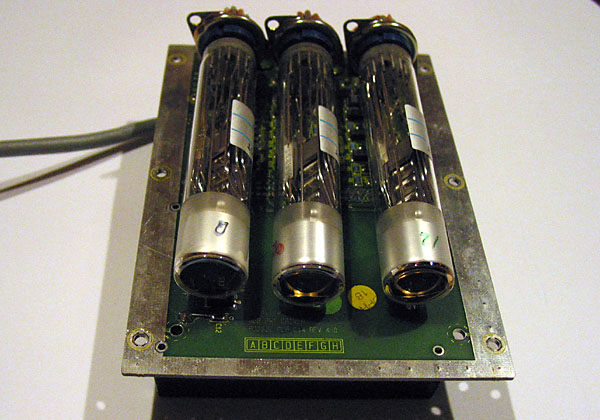
Photomultiplier tubes. Yeah, real vacuum tubes. I'm not sure these have filaments, but they have exotic plates kept at very high voltage. Incredibly sensitive, too. Basically, their plate current is proportional to the light flux entering the tube at the top surface.
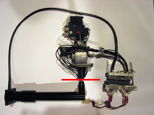
Here you see the two halogen bulbs in their brackets and the fiber optic cables (light pipes) extending from each one. One of these is a bundle of six individual cables. These terminate in a ferrule around the imaging lens, just as in a ring flash, and shine light at reflective targets. The red line represents the thickness and relative position of the drum.
The other (single) bundle goes inside that black tube to a lens at the end. It's shown in approximate placement opposite the optical pickup. This fella shines a spot of light from inside the drum, through film.
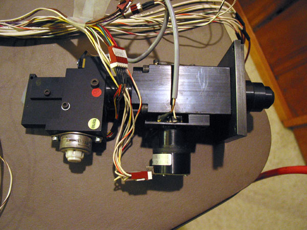
Optical pickup. More or less the heart of the machine. A wide flange on the
right mounts this to the optical bench. The lens is at the extreme right,
the light path is right to left. The black motor is for focus, the smaller
motor (silver colored case) is a linear stepper that selects one of eight
(or so) apertures.
Not shown are the three light pipes that go from the back of this assembly to the PMT assembly.
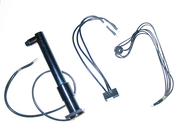
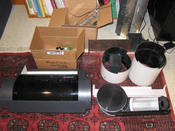
On the left. In a working scanner, this assembly is inside the drum, and shines a spot of focused white light through the target. The source of light (the free end of the light pipe) is one of the two MR-16 halogen lamps.
Middle: pipes from optical pickup assembly to PMT tube assembly.
Right: This weird assembly provides illumination for reflective targets. The source of this light is the second of the two MR-16 halogen lamps.
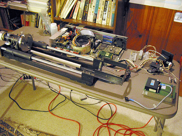
Partially reassembled, without the skin. The optical bench is the main thing you see here, with two massive linear bearings. The white tube hides the lead screw that drives the drum and drum motor back and forth.
Will it ever scan again?
That's the $64,000 question. I suppose it depends on just what's wrong with it. At the moment, it's not really communicating properly over its SCSI link, but it shows some signs of life. The drum spindle does its normal "dance" at power-up, moving back and forth a bit along its track. It responds properly to the "drum lock" button.
I feel like Dr. Sacks in the story (played by Robin Williams.) Pretty smart, but in this case, not quite smart enough to rescue the patient.
Part of what's bittersweet about all this is the dated and now failed technology. For example, the entire logic board on the right can now be replaced by one chip. Schematics appear to be unavailable. Rebuilding it would involve a huge effort in software. It could be fun, I suppose. But this is what I do in my day job. I'd really rather have a working scanner than a new project to soak up my spare time.
If the original engineering documents were available, I'd have a fighting chance. Without these, it's an uphill battle. A great learning experience, for sure.
How would 2005 Technology Help?
For starters, fiber optics seem like an odd choice for delivering light to the target. Why not use one or more of those super-bright LEDs and just put them where they're needed? Halogens and light pipes seem like a roundabout and inefficient way to go.
A modern film scanner probably would use a switching power supply. That big toroid is old hat. It would also use Firewire (IEEE 1394) or USB2 (maybe even USB High Speed) rather than SCSI. A handful of ICs could replace the entire logic board, including the A/Ds and motor control logic. See, for example Oasis Semiconductor.